3 Tips for Total CAD-GIS Integration


Translating from CAD to GIS and back can feel a little like a game of “telephone”. You know the game: you whisper a message around a circle and the last person says the message aloud—and the final message is always something way off. Likewise, by the time data gets back to its original format, we’ve lost valuable information.
We’ve discussed converting CAD to GIS. We’ve discussed converting GIS to CAD. Now how can we take data on a round-trip between CAD and GIS systems without losing anything important?
This post will explore the why, what, and how of total CAD-GIS integration.
Achieving interoperability between CAD, GIS, and more
Locking data in a single format is like keeping Bruce Banner in the confines of the Helicarrier. Eventually, the data is going to get angry and turn into a big green … wait, that’s not what I meant. Eventually, data will need to transform to reach its full potential.
It’s not enough to keep data in a single state: it must be free to move across systems, to integrate with other data, to mold into and exploit the strengths of other formats. It needs to be truly interoperable.
When working with CAD and GIS data, it’s often useful to enhance a CAD drawing with GIS information and attributes, then convert it back to the original format.

The key is to translate between CAD and GIS systems without losing any structure, geometry, or overall quality of the dataset.
CAD and GIS basics
When two data types are as different as CAD and GIS, converting freely between them can feel about as safe as dumping vinegar and baking soda inside a paper volcano. For a brief overview of these two data types, check out this blog post on converting CAD to GIS.
3 strategies for a CAD-to-GIS roundtrip

The basic idea of a CAD-to-GIS-to-CAD translation is to:
1. Record individual CAD components in the GIS dataset (e.g., block / cell names, basic symbology like line style and color).
2. Use this stored information to recreate the geometries and structures when writing the data back to CAD.
Below are some strategies for ensuring your translation is robust.
1. Use an attribute blob for CAD symbology
Often, CAD data includes so much complex symbology that the mere thought of carrying this to GIS and back is enough to induce panic. And I’m not making any assumptions about your social life, but you probably have better things to do than create a field in the GIS dataset for every single CAD attribute. However, this multitude of information needs to stay intact in order to recreate the data’s appearance when converting back to CAD.
A convenient way to do this is to pack the CAD symbology into a single blob field and store it that way in the GIS dataset (e.g. Esri Geodatabase). Then when converting back to CAD, you can unpack the blob into its original attributes without losing information. Bonus: packing the attributes into a blob is also accommodating for an evolving schema.
2. Convert unsupported geometries

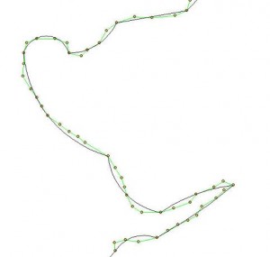
In CAD, it’s a spline. In GIS, it’s … um … well, it was a valiant effort. If a geometry isn’t supported by the GIS format, the data integrity will be lost in a conversion. For example, a true mathematical arc might get stroked and stored as line segments in an Esri Shapefile.
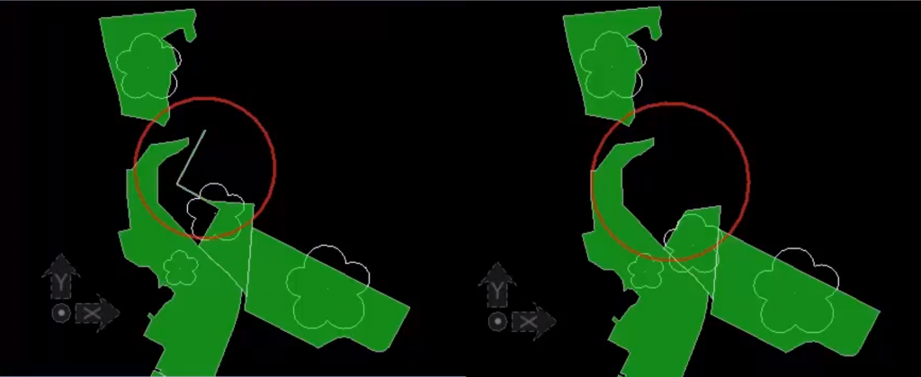
We might get a nice conversion between GIS point features and MicroStation cells or AutoCAD blocks, but other pieces don’t map so nicely. It’s therefore important to convert data back into its intended geometry—like smoothing line segments into a curve—when translating back to CAD.
3. Validate the CAD, GIS, and in-between data
Validation is always an important step in data transformations. In a CAD-to-GIS-to-CAD situation, it’s especially important to validate the data along the way. In fact, I’m going to argue that validating along the way is important in every project. Really.
One technique is to write a set of metadata records to document whatever changes are taking place. Another is to perform feature-by-feature quality checks to ensure the GIS-to-CAD translation is writing valid output. If an error is found, the features can be passed back to the GIS application to be cleaned up.
![]()
There are many strategies for integrating CAD and GIS data, and FME is designed to simplify this process. Be sure to read about specific techniques for converting CAD to GIS and converting GIS to CAD. What other strategies do you use to make your CAD and GIS data interoperable?


